
3D Injection Mold Design
High-precision 3D injection mold design and parametric tooling engineering. We transform complex part geometries into robust, high-efficiency production molds with comprehensive DFM, Moldflow simulation, and kinematic validation.
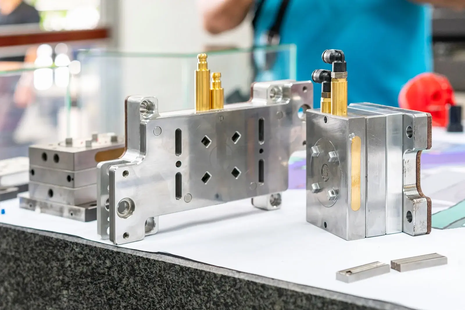
From Digital 3D CAD Concept to Production-Ready Tooling
Eliminating Costly Tooling Revisions Through Advanced 3D Parametric Mold Modeling
In modern plastic manufacturing, an injection molded component is only as reliable as the tooling that shapes it. At Engineering Innovation, our 3D injection mold design services bridge the gap between initial product styling and flawless production execution. By designing complete mold assemblies in full 3D solid geometry rather than traditional 2D wireframes, we capture every mechanical interaction before a single block of steel is machined.
Our tooling engineers evaluate every critical factor—volumetric resin shrinkage, parting surface continuity, thermal regulation, and dynamic side-action kinematics. The result is a robust, production-validated mold design that maximizes cycle efficiency, preserves dimensional stability across millions of shots, and accelerates time-to-market.
Comprehensive 3D Mold Design Services
Tailored Tooling Architectures Engineered for Performance, Durability, and Speed
Single & Multi-Cavity Mold Design
Balanced runner and gate distribution for single-cavity prototype molds or high-volume 2, 4, 8, 16, and 32-cavity production tools with uniform part weight and fill dynamics.
Hot Runner & Cold Runner Tooling
Engineering tailored delivery systems, from conventional two-plate and three-plate cold runner molds to advanced hot runner manifolds and valve-gated systems.
Complex Kinematics: Slides & Lifters
Resolving intricate side undercuts, internal threads, and deep snap-fits using mechanically driven angle pins, hydraulic core pulls, and collapsible cores.
Conformal Cooling & Thermal Design
Designing optimized cooling circuits with bubblers, baffles, and direct metal laser sintered (DMLS) 3D printed conformal cooling inserts to eliminate hot spots.
Rapid Prototype Tooling (Bridge Molds)
Fast-turnaround aluminum 7075-T6 and pre-hardened P20 steel tooling designed for rapid design validation, functional testing, and low-volume bridge production.
Production Tooling (SPI Class 101 & 102)
Hardened tool steel molds engineered for high-speed continuous manufacturing, capable of exceeding one million production cycles with minimal maintenance.
Our 3D Injection Mold Design Workflow
A Rigorous, Data-Driven Engineering Journey from Part Model to CAM Handoff
Part CAD Audit & Feasibility Review
We inspect your 3D component model for wall thickness uniformity, undercut conditions, draft angle compliance, and aesthetic parting lines.
Comprehensive DFM Analysis
Systematic Design for Manufacturability review identifying sink marks, gate locations, potential air traps, and structural rib adjustments.
Moldflow Simulation & Rheology
Advanced computational simulation analyzing melt front progression, injection pressure, clamp tonnage, fiber orientation, and cooling efficiency.
3D Parametric Tooling Architecture
Full solid modeling of the mold base, core, cavity, parting surfaces, slides, lifters, runner system, and waterline layouts in native CAD.
Kinematic Clash & Thermal Validation
Dynamic digital simulation verifying zero collision between ejector pins, slide actions, and moving plates during the complete opening and closing stroke.
2D Engineering Drawings & CAM Release
Generation of fully dimensioned 2D shop drawings with GD&T, BOM standard parts lists, and electrode models ready for CNC milling and sinker EDM.
Precision Core and Cavity Design
The Foundation of Part Accuracy, Aesthetic Excellence, and Tool Longevity
The heart of every injection mold is the core and cavity split. Our engineers employ advanced Class-A parametric surfacing techniques to develop smooth, robust parting lines that trace the exact contour of your component, eliminating flash and reducing witness lines on critical cosmetic surfaces.
For complex geometries with internal recesses, louvers, or screw bosses, we design precision shut-offs with a recommended 5° to 7° minimum draft angle to prevent steel-on-steel galling. Split inserts and sub-inserts are engineered with precision ground datum blocks, enabling easy benching, repair, and selective cooling channel placement.
Complex 3D Parting Line Modeling
Stepped, curved, and contoured parting surfaces created with tangent transitions to ensure clean mold sealing and flash-free components.
Robust Steel Shut-Off Geometry
Generous shut-off draft angles (5°–7°) that prevent tool rubbing and premature cavity wear under high injection clamping pressures.
Interchangeable Core & Cavity Inserts
Modular sub-inserts for high-wear areas, reducing long-term maintenance costs and facilitating quick engineering change orders (ECOs).
Precision Sinker EDM Electrode Modeling
Integrated copper and graphite electrode 3D CAD modeling with spark gap offsets for intricate ribs, sharp corners, and deep ribs.

Runner, Gate, Cooling, and Ejection Systems
Synchronizing Fluid Dynamics, Thermodynamics, and Machine Kinematics
Melt Delivery Systems
Designing cold runner (two-plate and three-plate) and hot runner systems engineered with naturally balanced flow lengths to ensure uniform cavity packing.
Optimal Ingestion Gate Geometry
Strategically located gating designed to minimize shear heating, eliminate gate blush, prevent weld lines in structural zones, and allow automated degating.
Cooling Circuit Engineering
Balanced cooling layouts maintaining uniform tool temperatures across both core and cavity halves to minimize cycle times and eliminate part warpage.
Reliable, Mark-Free Part Demolding
Calculated ejection force distribution ensuring components are removed smoothly without distortion, punch-through, or cosmetic push-pin witness marks.
Design for Manufacturability (DFM) Rules
Validating Plastic Part Geometry Before Finalizing Mold Tooling
Wall Thickness Uniformity
Maintaining constant nominal wall thickness prevents differential cooling rates, severe sink marks, and internal shrinkage voids.
Draft Angle Allocation
Adequate draft allows the part to release cleanly from the steel cavity without drag marks, scuffing, or excessive ejection pressure.
Rib-to-Wall Proportions
Properly proportioned structural ribs provide stiffness without creating localized thick sections that cause cosmetic surface sink.
Radii and Filleting
Replacing sharp inside corners with smooth radii eliminates high stress concentrations, improves resin flow, and extends mold tool life.
Boss Design & Coring
Screw bosses are cored out to the baseline to prevent heavy mass accumulation and sink marks on visible cosmetic surfaces.
Venting Provisions
Calculated perimeter venting channels allowing trapped air and gas to escape without allowing molten polymer to flash.
CAD Modeling and Simulation Validation
ThreeDInjectionMoldDesign.cadValidation.p1
Direct CAD File Formats Supported
We work directly with all major native and neutral neutral engineering files, preserving exact math surfaces without mesh degradation:
Materials and Engineering Considerations
Balancing Resin Shrinkage, Cycle Wear, and Steel Metallurgy
Common Polymer Resins & Shrinkage Factors
Tool steel cavities must be precisely scaled in 3D CAD to compensate for the specific volumetric shrinkage of the chosen polymer formulation:
| Polymer Resin | Volumetric Shrinkage | CAD Tooling Considerations |
|---|---|---|
| Polypropylene (PP) | 1.50% - 2.00% | High crystalline shrinkage; requires balanced cooling |
| ABS (Acrylonitrile Butadiene Styrene) | 0.40% - 0.70% | Amorphous resin; excellent dimensional stability |
| Polycarbonate (PC) | 0.50% - 0.70% | High viscosity; requires heated mold bases and generous draft |
| Nylon 6/6 (PA66) | 1.00% - 1.50% | Hygroscopic; shrinkage varies with fiber reinforcement |
| Polyoxymethylene (POM / Acetal) | 1.80% - 2.20% | High stiffness and lubricity; demands corrosion-resistant steel |
| PEEK / High-Performance Resins | 1.00% - 1.30% | High melt temp (380°C+); requires specialized tool heating |
Aluminum 7075-T6
Rapid thermal dissipation, fast machining for rapid prototypes and bridge tooling.
P20 Tool Steel
Pre-hardened general-purpose tool steel offering balanced toughness and polishability.
H13 Hardened Steel
Through-hardened hot-work steel with high wear resistance for abrasive glass-filled resins.
S136 / 420 Stainless
High-corrosion resistance and mirror polishability for optical parts and medical devices.
Applications and Industries Served
Proven Tooling Engineering for Critical Sectors Across the Globe
Automotive & Transportation
Under-the-hood structural brackets, interior dashboard bezels, sensor enclosures, and HVAC ducting with strict aesthetic and dimensional tolerances.
Medical & Healthcare Devices
Cleanroom-compatible Class 101 molds for diagnostic cassettes, syringe plungers, surgical device handles, and microfluidic cartridges.
Consumer Electronics & Enclosures
Thin-wall handheld housings, snap-fit wireless device chassis, acoustic enclosures, and elastomeric overmolded grips.
Industrial & Electrical Equipment
Heavy-duty terminal blocks, DIN-rail electrical enclosures, industrial valve components, and durable power tool housings.
Why Choose Engineering Innovation
End-to-End Mechanical Engineering Under One Agile Roof
Holistic Engineering Ecosystem
We don't design molds in isolation. Our multidisciplinary engineering team combines 3D CAD modeling, CNC machining, rapid 3D printing prototyping, and physical molding expertise to ensure designs are optimized for real-world manufacturing.
Advanced Predictive Simulation
Every design is digitally proven using Moldflow and kinematic clearance analysis, eliminating gate blush, air traps, and severe warpage before tool cutting commences.
Standardized Global Component Bases
We strictly adopt HASCO, DME, and Meusburger hardware standards, guaranteeing that replacement ejector pins, bushings, and springs are readily available worldwide.
Transparent, Milestone-Based Collaboration
From initial DFM review to final CAD package delivery, you receive transparent engineering reports, 3D clearance logs, and full intellectual property ownership.
Related Injection Mold and Tooling Services
Explore our specialized tooling and plastic injection mold engineering pages across the website.
Frequently Asked Questions
Clear Answers to Technical Questions Regarding 3D Injection Mold Design
Ready to Engineer Your Production Injection Mold?
Partner with Engineering Innovation for precision 3D CAD mold modeling, comprehensive DFM simulation, and manufacturing-ready tooling data.