
Precision Plastic Mold Design & Tooling Engineering Services
Engineered plastic mold tooling designed for zero-defect manufacturability. We specialize in high-precision single and multi-cavity injection molds, complex core and cavity splitting, thermal cooling circuits, hot runner integration, and complete toolmaker-ready CAD/CAM engineering.
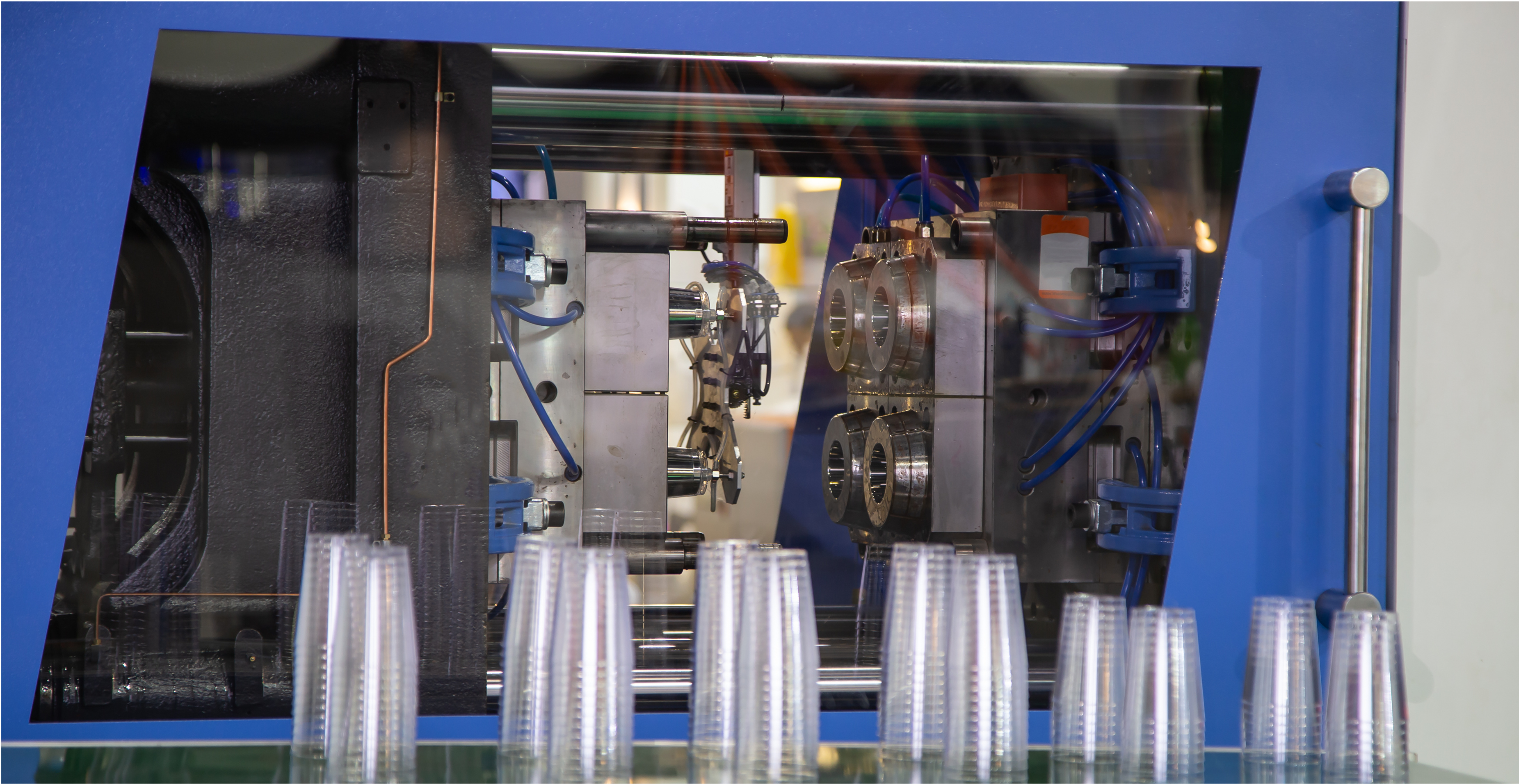
End-to-End Plastic Mold Engineering Capabilities
From initial part evaluation to complete tool assembly documentation, we design injection tooling tailored to your production volume, resin characteristics, and cycle time targets.
Core & Cavity Engineering
Precision parting line generation, shut-off angle calculation, and optimal block sizing to ensure flash-free mold closure and clean part definition.
- Complex shut-off surfaces
- Draft angle verification
- Interlocking taper locks
Single & Multi-Cavity Tooling
Designing production tooling from single-cavity prototype molds to balanced 8, 16, or 32-cavity high-volume production configurations.
- Naturally balanced runners
- Family mold layout balancing
- Uniform volumetric filling
Parting Line & Shut-Off Design
Strategic parting line placement to minimize visible witness marks, protect cosmetic aesthetics, and maintain tool longevity.
- Stepped & profiled parting surfaces
- Kiss-off shut-offs
- Wear-resistant guide surfaces
Gate & Runner Optimization
Engineered gating systems designed to minimize shear heating, prevent jetting, and position gate scars in non-functional areas.
- Sub-gates & pin gates
- Edge, fan & direct sprues
- Hot runner valve gate systems
Hot Runner & Cold Runner Systems
Application-specific feed engineering comparing cold runner three-plate tooling with internally heated, valve-gated hot runner manifolds.
- Manifold drop sizing
- Thermal gate tip selection
- Zero-scrap runnerless designs
Thermal & Cooling Channel Design
Strategically routed cooling circuits, bubblers, baffles, and conformal channels designed to maximize heat extraction and prevent post-mold warpage.
- Reynolds number turbulence control
- Baffle & bubbler circuits
- Conformal cooling pathways
Ejection & Demolding Mechanisms
Balanced ejection layouts featuring ejector pins, blade ejectors, stripper plates, mechanical side-action slides, and angle lifters for undercuts.
- Mechanical & hydraulic slides
- Cored undercut lifters
- Guided ejection return systems
Standard Mold Base Selection
Specifying industry-standard interchangeable mold bases (DME, Hasco, LKM, Misumi) for seamless global tool maintenance and spare parts availability.
- DME & Hasco standard plates
- A & B plate thickness optimization
- Precision leader pins & bushings
Complete 3D CAD & 2D GD&T Drawings
Fully modeled 3D solid assemblies and fully annotated 2D manufacturing drawings with complete Geometric Dimensioning and Tolerancing (GD&T).
- Native STEP/IGES/Parasolid files
- Complete Bill of Materials (BOM)
- Direct CAM & CNC-ready data
Anatomy of a High-Precision Injection Mold
An industrial injection mold is a precision mechanical assembly subjected to hundreds of tons of clamping force and thousands of bars of hydraulic pressure. Every component must be calculated to withstand repeated thermal expansion, mechanical shock, and cyclic fatigue.
Core & Cavity Inserts
CNC milled, EDM wire cut, and precision ground tool steel blocks that form the plastic part. Hardened to withstand repeated injection pressures and abrasive polymer flow.
Mold Base & Clamping Plates
Comprises top clamping plate, cavity plate (A-plate), core plate (B-plate), support plate, riser blocks, and bottom clamping plate to mount securely into the molding press.
Feed System (Sprue, Runner & Gate)
Routes molten plastic from the injection barrel nozzle into the cavity. Engineered with precise cross-sections to maintain balanced flow without excessive shear stress.
Cooling Circuitry
A network of drilled water channels, bubblers, and baffles designed to extract thermal energy quickly and evenly, accounting for over 70% of total cycle time.
Ejection & Undercut Release System
Ejector plates, pins, sleeves, slides, and angle lifters actuated by the machine ejector rod to release the part once cooled, with zero part scarring or pin push-through.
Guiding & Alignment Elements
High-precision guide pillars (leader pins), guide bushings, and tapered interlocks that ensure perfect core-to-cavity registration before clamping tonnage is applied.
Proactive DFM Reviews to Eliminate Tooling Risks
Catching design discrepancies in digital CAD prevents weeks of tool rework and thousands of dollars in tooling modifications. Our engineering DFM process systematically evaluates every geometry element for molding feasibility.
Draft Angle Optimization
Evaluating all vertical faces to ensure proper draft (typically 1° to 2° for smooth finishes, 3° to 5°+ for textured surfaces) to prevent drag marks, scratches, and sticking in the cavity.
Wall Thickness Uniformity
Identifying localized thick sections that cause sink marks, internal voids, and differential shrinkage warpage. Recommending coring-out and transition blends.
Undercut & Demolding Evaluation
Pinpointing design geometry perpendicular to the draw direction, optimizing part features to eliminate slides where feasible or designing compact mechanical lifters.
Rib & Boss Design Ratio
Calculating rib thicknesses to nominal wall ratios (typically 40%–60%) to provide structural rigidity while preventing aesthetic sink marks on visible exterior surfaces.
Gate Location & Knit Line Management
Positioning gates to direct melt flow toward critical areas, ensuring weld lines occur in structurally non-critical zones and venting is placed at end-of-fill areas.
Radius & Corner Transitions
Replacing sharp internal corners with calculated fillets (R = 0.5t) to reduce stress concentration factors from 3.0 down to 1.5, dramatically improving impact resistance.
Mold Flow Simulation & Thermal Balance Optimization
Mold flow simulation bridges theoretical physics and tooling geometry. By analyzing polymer viscosity, melt temperature, and mold thermal gradients, we eliminate trial-and-error prototyping before tooling fabrication.
Filling Pattern & Flow Front Velocity
Visualizing the advancing melt front to detect hesitation, unbalanced multi-cavity filling, pressure spikes, and premature freezing.
Weld Lines & Air Trap Prediction
Predicting where converging flow fronts meet to evaluate weld line tensile strength and ensure intentional mold venting at the final fill points.
Thermal Dissipation & Conformal Cooling
Analyzing heat flux across core and cavity inserts, engineering balanced cooling loops to achieve uniform part solidification across varying wall thicknesses.
Volumetric Shrinkage & Warpage Control
Calculating post-mold deflection caused by differential volumetric shrinkage, enabling mold steel pre-compensation to hold tight drawing tolerances.
Our Step-by-Step Mold Design Process
A disciplined, transparent engineering methodology ensuring seamless toolmaker transition and first-trial (T1) part validation.
Requirements Review & Resin Audit
We analyze part CAD files, production volume forecasts, polymer resin specifications (shrinkage, melt flow index), cosmetic requirements, and molding press specifications.
DFM Review & Tooling Feasibility
A comprehensive Design for Manufacturability audit covering draft angles, wall thickness, parting lines, and undercut management, delivered with recommended design improvements.
Rheological Mold Flow Analysis
Simulating fill, pack, cooling, and warp behavior to optimize gate count, gate placement, injection pressures, clamp tonnage estimates, and cycle time windows.
Core/Cavity & Parting Architecture
Splitting part geometry into core and cavity blocks, designing complex shut-off surfaces, and establishing parting line integrity with precision taper interlocks.
Subsystem Design & Mechanical Actions
Routing cooling channels, engineering ejector pin layouts, designing mechanical side slides, hydraulic cores, angle lifters, and hot runner manifold integrations.
Full 3D CAD & 2D Tooling Drawings
Final assembly 3D modeling, component BOM generation, tolerance stack-up analysis, and fully annotated 2D GD&T manufacturing drawings for CAM/CNC machining.
Tool Steel Selection & SPI Mold Classifications
Selecting the correct mold steel is a balance between raw material cost, machining machinability, wear resistance, and total production volume expectations.
P20 / 1.2311
SPI Class 103General prototyping, medium-volume production (up to 500k shots), standard commodity resins (PP, PE, ABS). Excellent machinability and Polishability.
718H / 1.2738
SPI Class 102/103Large mold bases, automotive exterior/interior components, enhanced core hardness uniformity compared to standard P20.
H13 / 1.2344
SPI Class 101/102High-volume abrasive resins (glass-filled nylon, PBT), high-temperature molding, sliding components, and long-life core/cavity inserts.
S136 / 420 SS
SPI Class 101Medical devices, optical lenses, corrosive resins (PVC, fluoropolymers), mirror-polish SPI-A1 finishes, and high-cleanroom environments.
Aluminum 7075-T6
SPI Class 104/105Rapid prototype tooling, bridge tooling (1k to 25k shots), accelerated thermal conductivity for rapid cycle evaluation.
Industries Relying on Our Plastic Mold Engineering
Delivering high-precision tooling designs across mission-critical technical sectors.
Automotive & Transportation
Under-the-hood structural brackets, interior bezels, connectors, HVAC ducting, and lighting housings requiring tight dimensional stability and high-impact polymers.
Medical & Healthcare Devices
Disposable diagnostic cartridges, surgical instrument housings, luer fittings, and cleanroom-compliant medical components designed with stainless steel tooling.
Consumer Electronics & Enclosures
Thin-wall handheld device enclosures, wearable housings, snap-fit battery covers, and high-cosmetic bezels demanding flawless SPI-A2 surface finishes.
Industrial & Fluid Handling
High-pressure pipe fittings, industrial pump impellers, heavy-duty electrical switchgear, and chemical-resistant valves engineered for harsh environments.
Precision Tooling Engineering with In-House Synergy
We bridge the gap between abstract CAD modeling and physical toolroom reality.
Real Toolroom & Machining Synergy
Our designers work alongside experienced CNC machinists and toolmakers. We design molds that are practical to machine on 3-axis and 5-axis CNCs, sinker EDMs, and wire EDMs without unneeded complexity.
Vendor-Neutral CAD/CAM Deliverables
You retain full ownership of native 3D solid models, 2D GD&T manufacturing drawings, and complete Bills of Materials (BOM), ready to hand off to any tooling shop worldwide.
Rigorous DFM & Simulation First
Every design is validated through gate, cooling, and mold flow analysis before final drafting, avoiding the expensive trial-and-error cycle at the molding press.
Comprehensive Engineering Support
From initial resin selection and part optimization to mold base customization and toolmaker fabrication support, we provide responsive technical collaboration.
Related Mold Design & Manufacturing Resources
Explore our full spectrum of tooling design, rapid prototyping, and injection molding services.
3D Injection Mold Design & CAD Simulation
Comprehensive 3D digital CAD modeling, mold simulation, and tool splitting.
Plastic Part Design & DFM Services
Expert component-level plastic part optimization and DFM engineering.
Plastic Molding Design Services
Custom tooling engineering, multi-cavity mold layouts, and prototype tooling.
Plastic Injection Molding Production
High-volume contract molding, production runs, and quality inspection.
Comprehensive Injection Molding Guide
In-depth engineering guide covering molding parameters, resins, and tool design.
Injection Mold Tooling & Fabrication
Precision mold base machining, cavity milling, and EDM tooling fabrication.
Injection Mold Design USA
Dedicated mold engineering, CAD tooling, and prototyping for the US market.
Injection Mold Design UK
Professional injection mold design, tooling simulation, and engineering for the UK.
Common Questions About Plastic Mold Design
Clear, technical answers to critical questions regarding tooling design, engineering deliverables, and project feasibility.
Ready to Engineer Your Next Injection Mold?
Connect with our tooling design engineers for a comprehensive DFM assessment and detailed mold engineering consultation.