
Injection Molding Tool Design & Production Tooling Engineering
High-precision injection molding tool design and production tooling engineering. We transform complex part geometries into robust, high-efficiency production molds with comprehensive DFM, Moldflow simulation, kinematic slider validation, and vendor-neutral 2D/3D CAM deliverables.
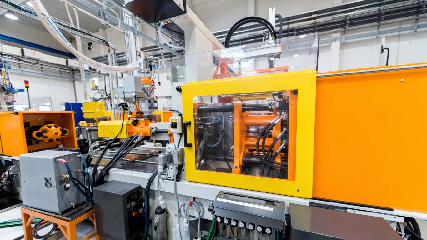
What is Injection Molding Tool Design?
Bridging Component Design and Production-Scale Tool Fabrication
Unlike general plastic part design (which focuses on end-use geometry and aesthetics) or basic 3D CAD modeling (which constructs digital solids), Injection Molding Tool Design is the rigorous engineering discipline of developing production-ready tooling capable of withstanding millions of clamping tons, rapid thermal cycles, and high-pressure resin flow. Tool design engineers resolve the complex physics between polymer melt rheology, tool steel metallurgy, differential thermal expansion, side-action mechanical kinematics, venting dynamics, and balanced ejection without compromising part tolerance or cycle efficiency.
Core Tooling Architecture & Subsystems
Engineered Subsystems for Repeatable, High-Speed Injection Cycles
Core & Cavity Inserts
The primary tooling elements that shape the internal and external geometry of the molded part. We engineer pocketed insert designs with precision ground shut-offs, stepped or contoured parting lines, and calibrated thermal expansion relief to maximize tool rigidity and simplify field maintenance.
Sliders & Mechanical Lifters
Actuated tooling components engineered to release external undercuts, side holes, snap-fits, and internal threads that cannot clear the main mold opening stroke. We design angle pin cam slides with positive heel-block locking and articulated lifters for reliable kinematic clearance.
Runner, Gate & Hot Runner Systems
The melt delivery network engineered to transport molten polymer from the machine nozzle into each cavity with balanced pressure, uniform temperature, and minimal shear stress. We balance cold runners geometrically and configure sequential hot runner valve gates.
Cooling Circuits & Ejection Systems
Thermal management and mechanical ejection systems engineered in tandem. Cooling accounts for 70% to 80% of total cycle time; we design turbulent-flow waterlines, baffles, bubblers, and high-conductivity inserts paired with rigid guided ejector plates.
SPI Mold Tooling Classification Standards
Matching Tooling Construction to Total Production Volume and Commercial Lifespan
The Society of the Plastics Industry (SPI / PLASTICS) classification standard defines mold construction requirements based on anticipated production lifecycle, cavity steel metallurgy, cooling circuit complexity, and guidance hardware. Selecting the appropriate SPI class ensures capital efficiency without risking premature tool failure.
| SPI Class | Expected Cycle Life | Cavity / Core Metallurgy | Mold Base & Construction Features | Maintenance & Application Profile |
|---|---|---|---|---|
| Class 101 | 1,000,000+ cycles | Through-hardened tool steel (48–54 HRC, H13, S136 stainless) | Guided ejector plates, hardened slide wear plates, temperature-controlled water circuits, corrosion resistance | Continuous high-volume production, medical, packaging, automotive |
| Class 102 | 500,000 – 1,000,000 cycles | Hardened tool steel (48 HRC minimum, H13, 420 SS) | Guided ejection, hardened slide components, plated cooling channels, standard DME/HASCO base | Medium-to-high volume production, consumer electronics, industrial housings |
| Class 103 | 100,000 – 500,000 cycles | Pre-hardened tool steel (28–36 HRC, P20, 718H) | Standard mold base, conventional drilled cooling lines, standard ejector pin configuration | Most popular production tooling standard, commodity polymers, balanced capital cost |
| Class 104 | 10,000 – 100,000 cycles | Mild steel or pre-hardened aluminum (P20 or 7075-T6) | Basic mold base, limited cooling circuits, standard ejector pins without guided plate bushings | Low-volume production, pilot production runs, bridge tooling before mass automation |
| Class 105 | < 10,000 cycles (500–5,000) | Aluminum 7075-T6, mild steel, or cast metal | Cast or bolted mold frame, manual inserts or hand-loaded cores, minimal cooling channels | Functional prototyping, design validation, market trial quantities |
Tool Steel Selection & Metallurgical Guidelines
Balancing Resin Chemistry, Abrasiveness, Polishability, and Tool Longevity
Selecting the optimal mold steel requires a comprehensive evaluation of resin characteristics (abrasive glass fibers, corrosive outgassing, melt temperature), surface finish requirements (optical mirror finish vs. EDM texture), thermal conductivity, and total expected production cycles.
P20 / 1.2311
SPI Class 103 / 104General-purpose production tool steel. Excellent machinability, uniform hardness throughout large blocks, and good polishability for commodity resins (PP, PE, ABS, PS). Eliminates heat treatment distortion risks.
718H / 1.2738
SPI Class 102 / 103Modified vacuum-degassed pre-hardened steel with added nickel. Provides superior core hardness uniformity in large mold bases and automotive exterior/interior tooling with enhanced photo-etch texturing response.
H13 / 1.2344
SPI Class 101 / 102Premium hot-work chromium-molybdenum tool steel. Exceptional toughness, resistance to thermal fatigue cracking (heat checking), and high resistance to abrasive wear from glass-filled resins (PA-GF, PBT-GF).
S136 / 420 Stainless
SPI Class 101High-chromium martensitic stainless steel offering extreme corrosion resistance and mirror polishability to SPI-A1 standards. Essential for medical devices, optical lenses, cleanroom molding, and corrosive resins (PVC, fluoropolymers).
Aluminum 7075-T6
SPI Class 104 / 105High-strength aerospace alloy with nearly four times the thermal conductivity of steel. Ideal for rapid prototype tooling, bridge tooling (1k–25k shots), and accelerated cycle evaluation with reduced thermal cycle times.
SPI Mold Surface Finishes & VDI Texture Standards
Specifying Polish Grades, Light-Scattering Textures, and Demolding Draft Angles
Tool surface finish dictates both cosmetic part aesthetics and demolding release dynamics. We polish tool cavities to precise SPI (Society of the Plastics Industry) and VDI 3400 spark erosion scales, matching proper draft angles to prevent micro-galling and dragging during ejection.
| SPI / VDI Grade | Finishing Method | Roughness (Ra) | Typical Application | Min. Added Draft |
|---|---|---|---|---|
| SPI A-1 | Grade #3 Diamond Buff (3000+ grit) | 0.012 - 0.025 µm | Optical mirrors, transparent light guides, ophthalmic lenses | 0.5° - 1.0° |
| SPI A-2 | Grade #6 Diamond Buff (6000 grit) | 0.025 - 0.05 µm | High-gloss consumer electronics, transparent bezels & display covers | 1.0° |
| SPI A-3 | Grade #15 Diamond Buff (3000 grit) | 0.05 - 0.10 µm | Gloss cosmetic medical housings, shiny automotive interior parts | 1.0° |
| SPI B-1 | 600 Grit Fine Emery Paper | 0.05 - 0.10 µm | Semi-gloss housings, completely masks minor CNC milling tracks | 1.0° - 1.5° |
| SPI B-2 | 400 Grit Emery Paper | 0.10 - 0.15 µm | Medium-luster industrial enclosures, commercial equipment panels | 1.5° |
| SPI B-3 | 320 Grit Emery Paper | 0.28 - 0.38 µm | Low-luster internal structural covers, concealed battery compartments | 1.5° |
| SPI C-1 | 600 Stone Abrasive | 0.35 - 0.40 µm | Micro-matte industrial finish, zero glare reflection on instruments | 1.5° - 2.0° |
| SPI C-2 | 400 Stone Abrasive | 0.45 - 0.55 µm | Standard non-cosmetic industrial brackets, durable matte cases | 2.0° |
| SPI C-3 | 320 Stone Abrasive | 0.63 - 0.85 µm | Coarse matte under-hood brackets, internal automotive HVAC ducts | 2.0° - 2.5° |
| SPI D-1 / VDI 18-24 | Dry Blast Glass Bead (matte texture) | 0.90 - 1.40 µm | Satin textured consumer handles, scuff-resistant & fingerprint-proof | 2.5° - 3.0° |
| SPI D-2 / VDI 27-30 | Dry Blast #240 Oxide Sand | 1.40 - 2.50 µm | Heavy textured non-slip grips, rugged power tools & handheld gear | 3.5° - 4.5° |
| SPI D-3 / VDI 33-39 | Coarse #24 Oxide Sand Blast | 3.20 - 6.30 µm | Deep tactile industrial handle grip, outdoor rough machinery | 5.0° - 7.0° |
Gate, Runner, and Melt Delivery Systems
Balancing Pressure Drops, Shear Heating, and Part Aesthetics
The melt delivery system governs resin flow front velocity, packing efficiency, and weld line positioning. Selecting between cold and hot runner systems and determining precise gate geometries directly impacts scrap rates, cycle times, and post-molding trimming operations.
| Design Parameter | Cold Runner Systems | Hot Runner Systems |
|---|---|---|
| Melt Delivery & Temperature | Solidifies with each shot in unheated runner channels; ejected as scrap or regrind | Maintained in molten state within heated manifold nozzles; zero runner solidification |
| Cycle Time Impact | Cycle time limited by thickest runner section cooling time | Reduced cycle times (10% to 35% faster) governed solely by part wall thickness |
| Material Scrap & Regrind | Produces 15% to 50% scrap by weight; requires regrind granulators | Virtually zero runner scrap; direct gate entry into cavity |
| Tooling Complexity & Cost | Lower initial tooling cost; simple mechanical 2-plate or 3-plate mold base | Higher upfront capital investment; requires multi-zone PID temperature controllers |
| Multi-Cavity Balance Control | Geometrically balanced runners required to prevent cavity overpacking | Precise independent thermal or valve-gate timing across all cavities |
Standard rectangular gate positioned on the parting line, feeding into the component sidewall.
Angled conical gate tunneling below the parting line into the side or underside of the part.
Curved sub-gate that curls around the core to feed the interior or bottom of the component.
Mechanically driven shut-off pin that closes flush with the cavity surface after cavity packing.
Cooling Circuit Dynamics and Ejection Engineering
Uniform Heat Dissipation and Safe, Distortion-Free Part Demolding
Thermal Cooling Circuits
Turbulent Flow Reynolds Number Optimization
Cooling channels are sized and positioned to maintain a Reynolds number above 4,000, ensuring turbulent coolant flow that yields maximum heat transfer coefficient between tool steel and circulating fluid.
Deep Core Baffles and Bubblers
Deep core projections that cannot accommodate through-drilled waterlines utilize brass or stainless baffles and bubblers, forcing fresh coolant directly to the tip of tall ribs and core pillars.
High-Conductivity Inserts & Conformal Cooling
For stubborn thermal hot spots, copper-beryllium (CuBe) inserts or additive manufactured (DMLS) conformal cooling inserts with organic curving waterlines are integrated to eliminate differential shrinkage.
Mechanical Ejection Systems
Balanced Ejector Pin Distribution
Ejector pins are placed directly beneath ribs, bosses, and perimeter sidewalls where demolding friction is highest, distributing ejection force evenly to prevent punch-through or stress whitening.
Stripper Plates & Sleeve Ejectors
For cylindrical, tubular, or thin-walled components, continuous stripper rings or 360° sleeve ejectors are engineered to exert uniform perimeter force without deforming thin part lips.
Pneumatic Air Poppet Valves
For deep, airtight container geometries, pneumatic poppet valves inject compressed air at the bottom of the core before mechanical ejection, breaking the vacuum seal and eliminating suction drag.
Tooling DFM & Defect Prevention Engineering
Addressing Moldability Challenges Before Steel is Cut
Minimum 0.5° on interior cores, 1.0°–1.5° on exterior cavities, and 1° per 0.025 mm of texture depth (VDI 3400 / Mold-Tech).
Design minimum 3° to 5° shut-off angles on side-action slides, bypass holes, and parting line transitions.
Maintain internal fillet radii at R ≥ 0.5 × wall thickness and external radii at R = 1.5 × wall thickness.
Machine micro-vents (0.015 mm to 0.038 mm depth depending on polymer viscosity) around the parting line perimeter.
Enforce rib base thickness between 40% and 60% of adjacent nominal wall thickness.
Apply differential isotropic and anisotropic shrinkage factors tailored to the specific resin and fiber orientation.
Resin-Specific Wall Thickness & Tool Shrinkage Guidelines
Calibrating Cavity Cut Dimensions and Flow Lengths to Thermal Polymer Behaviors
Every thermoplastic resin contracts at a distinct volumetric rate during the thermal transition from melt to solid. We scale tool cavity dimensions against verified resin shrinkage coefficients while respecting recommended wall thickness bounds to maintain fill pressures.
| Polymer Family | Common Engineering Grades | Wall Thickness (Min - Max) | Linear Shrinkage Rate | Flow Ratio (L/T) | Tool Engineering Considerations |
|---|---|---|---|---|---|
| ABS (Acrylonitrile Butadiene Styrene) | Lustran, Cycolac, Magnum | 1.14 mm - 3.50 mm | 0.4% - 0.7% | 150:1 | Extremely predictable shrink; excellent dimensional stability for tight-tolerance snap-fits and electronic enclosures. |
| Polycarbonate (PC) | Lexan, Makrolon, Calibre | 1.00 mm - 3.80 mm | 0.5% - 0.8% | 100:1 | High melt viscosity requires generous gating (>=60% wall) and high tool oil temperatures (85°C to 120°C) to avoid residual molded-in stress. |
| PC/ABS Blend | Bayblend, Cycoloy, Pulse | 1.20 mm - 3.50 mm | 0.5% - 0.7% | 120:1 | Combines PC mechanical strength with ABS melt flow; ideal for structural electronic bezels and medical diagnostic enclosures. |
| Nylon 6/6 (PA66) | Zytel, Durethan, Ultramid | 0.75 mm - 2.80 mm | 1.0% - 2.5% | 200:1 | Semi-crystalline with anisotropic shrink; requires precise micro-venting (0.012-0.018 mm) to eliminate flash and vacuum dry cycling. |
| Polypropylene (PP) | Pro-fax, Moplen, Total PP | 0.65 mm - 3.80 mm | 1.2% - 2.5% | 250:1 | High volumetric shrinkage; requires strictly balanced conformal cooling circuits to prevent differential shrinkage warpage on flat faces. |
| POM (Acetal / Delrin) | Delrin 500, Hostaform, Celcon | 0.80 mm - 3.00 mm | 1.8% - 3.5% | 150:1 | High crystallization rate; demands gradual wall thickness transitions and generous gate lands to suppress internal shrink voids. |
| PEEK (Polyetheretherketone) | Victrex PEEK, KetaSpire, Zeniva | 1.20 mm - 3.50 mm | 1.2% - 1.8% | 100:1 | Demands premium hardened tool steel (H13 or S136 at 52 HRC) with specialized cartridge or thermal oil heating reaching 160°C to 200°C. |
Tooling Defect Diagnosis & Mechanical Correction Matrix
Resolving Part Flaws at the Tool Design Phase Before Steel is Cut
Over 80% of injection molding part defects stem directly from mold geometry, runner sizing, venting depths, or thermal imbalances. Here is how our tooling engineers eliminate defects systematically inside CAD:
Sink Marks & Internal Voids
Thick wall intersections, ribs exceeding 60% of nominal wall, or premature gate freeze preventing cavity packing.
Core out thick sections with mechanical core pins, taper ribs down to 45%-50% nominal wall, and enlarge runner/gate lands.
Part Warpage & Post-Mold Bowing
Asymmetric cooling rates across core vs cavity, non-uniform wall thickness, or orientation-dependent molecular shrinkage.
Design dual-circuit conformal cooling channels, equalize thermal transfer with beryllium-copper inserts, and add stiffening crown draft.
Weld Lines & Knit Lines
Converging polymer melt fronts around core pins or multiple gates experiencing excessive thermal drop before fusion.
Re-position gates to direct weld lines into non-aesthetic, low-stress zones; add flow tabs and peripheral micro-vents at the seam.
Flash & Parting Line Burrs
Inadequate clamping shut-off land contact area, mold deflection under high tonnage, or over-deep venting.
Enlarge parting shut-off land to >=25mm, add 0.03mm pre-load to core inserts, and machine perimeter vents to exact resin flash depths.
Short Shots (Incomplete Fill)
Excessive flow length-to-thickness ratio (L/T), restricted gate lands, or trapped air pockets creating counter-pressure.
Increase gate orifice and runner cross-section, utilize sequential valve gating on large geometries, and vent all blind ribs to atmosphere.
Burn Marks & Dieseling
Trapped air compressed at the terminal filling front without a vent path, reaching adiabatic combustion temperature (dieseling).
Place ejector pin flats (0.02 mm clearance) directly at the terminal burn point or insert micro-porous venting steel inserts (Porcerax II).
Our Injection Molding Tool Design Workflow
A Systematic, Milestone-Driven Tooling Engineering Methodology
CAD Geometry & Resin Shrinkage Review
We analyze your 3D CAD part model (STEP, IGES, Parasolid), review polymer specifications, and calculate flow-direction vs. cross-flow volumetric shrinkage allowances.
Comprehensive Tooling DFM Review
We evaluate parting lines, draft angle adequacy, wall thickness consistency, gating strategy, and side-action mechanical requirements to identify potential moldability risks.
3D Tool Assembly & Kinematic Design
We build the complete parametric 3D mold tool assembly, including core/cavity inserts, standard DME/HASCO mold base, sliders, lifters, cooling circuits, and ejector grid.
Moldflow Thermal & Filling Simulation
We execute finite element Moldflow simulations to validate fill time, injection pressures, clamp tonnage, weld line locations, cooling uniformity, and predicted part warpage.
Toolmaker-Ready 2D/3D Handover
We generate fully dimensioned 2D fabrication drawings with GD&T tolerances, complete Bill of Materials (BOM), and export CAM-ready STEP files ready for CNC machining and EDM.
Comprehensive Engineering Deliverables Package
Complete Technical Documentation Ready for Your Toolroom or Contract Toolmaker
3D Master Assembly Models
Fully constrained parametric 3D CAD solid models of the entire mold assembly, including mold base plates, clamping slots, locating rings, and sprue bushings.
Core & Cavity Solid Inserts
Independent, fully modeled core and cavity solid insert blocks with pre-applied resin shrinkage compensation, EDM clearance offsets, and shut-off drafts.
Standard Mold Base Bill of Materials (BOM)
Itemized catalog hardware schedule specifying commercial part numbers for DME, HASCO, Meusburger, or MISUMI standard components, pins, and springs.
2D Toolmaker Fabrication Drawings
Complete 2D drafting package with ASME Y14.5 / ISO GD&T annotations, fit tolerances (H7/g6, etc.), datum references, and surface finish callouts.
Cooling Circuit Schematics
Schematic drawings depicting water channel diameters, baffle orientations, bubbler placements, O-ring groove locations, and supply/return NPT/BSPT port locations.
Moldflow Simulation Analysis Report
In-depth engineering simulation report documenting fill time, pressure at V/P switchover, shear rate, volumetric shrinkage, weld lines, and warpage prediction.
Tooling Cost Drivers & Strategic Budget Optimization
Maximizing Tooling ROI: Balancing Upfront Capital Investment Against Per-Part Unit Cost
Tool engineering directly governs both your initial tooling investment (CAPEX) and long-term part production unit cost (OPEX). We engineer tooling architectures tailored to your exact production volumes through proven value-engineering practices:
MUD (Master Unit Die) Insert Systems
For validation pilots and short-to-medium runs (1,000 to 25,000 parts), we build precision core/cavity inserts that slot into standardized master mold frames—saving up to 45% in tooling steel and machining lead times.
Slider & Mechanical Cam Elimination
Through smart DFM part redesign, we replace costly mechanical side-actions and lifters with line-of-draw shut-offs and pass-through core pins, drastically lowering tool complexity and maintenance downtime.
Cavitation Optimization Analysis
We mathematically calculate the ideal balance between single-cavity prototype tools, 2-cavity bridge molds, and 4-to-16-cavity family tools based on required press tonnage, cycle times, and annualized part volumes.
Selective Precision Tolerancing
We apply micro-tolerances (±0.005 mm) strictly to critical shut-offs, parting line registers, and seal tracks, while relaxing non-mating mold base plates to standard ISO tolerances to eliminate needless machining cost.
Frequently Asked Questions About Tool Design
Clear, Expert Answers to Common Tooling Engineering Questions
Related Injection Mold & Tooling Capabilities
Explore Our Full Spectrum of Specialized Injection Mold Design and Tooling Services
Plastic Mold Design Services
End-to-end plastic mold design services covering part manufacturability, core/cavity splitting, and production-ready mold designs.
3D Injection Mold CAD Modeling
Parametric 3D solid modeling, kinematic slider simulation, and digital assembly validation for complex mold assemblies.
Injection Mold Design & Manufacturing
Full-lifecycle injection mold making, high-cavity tool building, and physical tooling fabrication shop services.
Plastic Injection Molding Design & DFM
Specialized part-level DFM optimization, wall thickness balancing, cooling analysis, and defect prevention principles.
Comprehensive Injection Molding Guide
Complete technical guide covering injection molding parameters, polymer shrinkages, and tooling mechanics.
Precision Mold Tooling & Fabrication
High-accuracy mold base machining, custom core/cavity inserts, and EDM precision tooling services.
Plastic Molding Design Services
Custom plastic mold engineering, multi-cavity tool layouts, and prototype-to-production tooling solutions.
Precision CNC Machining for Mold Inserts
Tight-tolerance multi-axis CNC milling and Swiss turning for mold cavity inserts, precision slides, and copper electrodes.
Ready to Engineer Your Injection Molding Tooling?
Ensure your mold is engineered for zero-defect production, optimal cycle times, and maximum tool longevity before cutting steel. Discuss your part geometry, production volume, and tooling specifications with our engineering team.