
Injection Mold Manufacturing & Custom Tooling Fabrication
Turn complex 3D part geometries into hardened, high-efficiency production injection molds. From 5-axis CNC roughing and precision wire EDM to multi-cavity tool building, blue-matched bench fitting, and comprehensive T1 sampling reports.
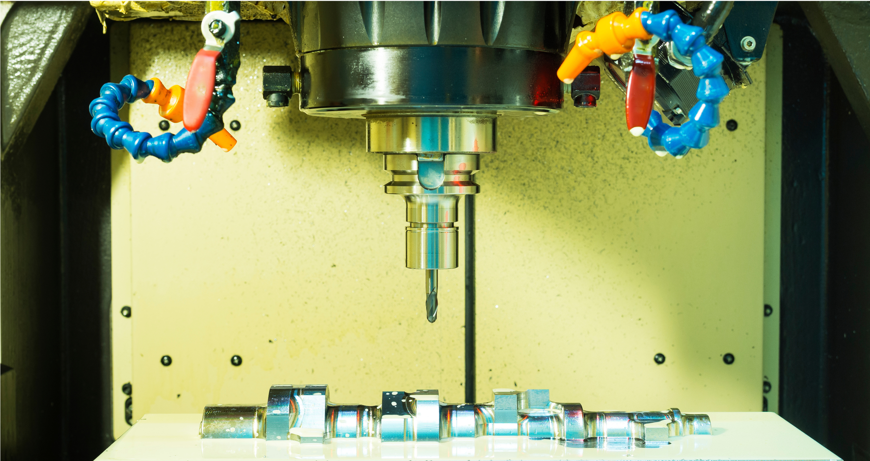
Industrial Toolmaking Standards & Capacity
Rigorous manufacturing tolerances and full-spectrum machinery engineered for zero-defect mold production.
Full-Spectrum Injection Mold Architecture
Precision-engineered tool construction designed for thermal equilibrium, kinematic longevity, and seamless production cycles.
Core & Cavity Precision Blocks
Through-hardened premium steel inserts fitted with optical blue-matching into standardized mold bases.
Standardized Mold Base Systems
Heavy-duty structural tool bases ensuring rigidity under high clamping tonnage and continuous high-speed cycling.
Kinematic Slides, Lifters & Core Pulls
Mechanical angle pins, hydraulic cylinders, and collapsible cores for complex part undercuts and internal threads.
Guided Ejection & Stripper Plates
Precision-ground guided ejector assemblies ensuring clean part release without pin drag, witness marks, or pin binding.
SPI Mold Classification Standards
We fabricate custom molds aligned with the Society of the Plastics Industry (SPI) guidelines, matching tool steel and mechanics to your target production volume.
| SPI Class | Rated Cycle Life | Steel Specification | Typical Application | Maintenance Protocol |
|---|---|---|---|---|
| Class 101 | 1,000,000+ Cycles | H13, S136, 420SS (≥48 HRC) | High-volume packaging, automotive, consumer electronics | Extremely low, guided ejection, temperature-controlled waterlines |
| Class 102 | Up to 1,000,000 Cycles | H13, 718H, P20 Hardened (≥40 HRC) | Medium-to-high production parts, technical enclosures | Low maintenance, replaceable wear components |
| Class 103 | Up to 500,000 Cycles | P20, NAK80 (28–36 HRC) | Standard commercial production, industrial housings | Periodic maintenance, standard mold bases |
| Class 104 | Up to 100,000 Cycles | P20, Mild Carbon Steel (HRC 28) | Low-volume pilot runs, limited market runs | Basic tooling, economical production |
| Class 105 | < 500 Cycles | 7075-T6 Aluminum / Mild Steel | Rapid prototype verification, pre-production clinical trials | Experimental tooling, manual hand loads |
Premium Mold Steels & Metallurgy Matrix
Matching steel grades to abrasive resin fillers, optical polish demands, and extreme thermal requirements.
S136 / Stavax (ESR)
Class 101Medical, optical lenses, corrosive PVC/flame-retardant resins, diamond mirror polish.
H13 Tool Steel
Class 101Heavy-duty engineering plastics, glass-filled nylons (PA-GF), high-cycle structural components.
718H / P20+Ni
Class 102–103Large automotive bezels, appliance housings, high-polish cosmetic exterior parts.
NAK80
Class 102–103High-definition electrical housings, zero pin-porosity optical finishes, EDM textured parts.
P20 Standard
Class 103–104Commercial consumer goods, general-purpose ABS, PP, and PE injection molding.
Beryllium Copper (Ampco)
Insert SpecificHigh thermal dissipation core pins, thin deep ribs, hot spot cooling cycle acceleration.
SPI & VDI Surface Finishing Standards
From optical mirror polish to heavy EDM industrial textures, our in-house finishing specialists deliver calibrated mold finishes.
| SPI / VDI Grade | Finishing Method | Surface Roughness (Ra) | Typical Application | Min Recommended Draft |
|---|---|---|---|---|
| SPI A-1 | Diamond Paste (Grade 3) | Ra 0.012 – 0.025 µm | Optical lenses, light pipes, high-gloss transparent medical parts | 0.5° – 1.0° |
| SPI A-2 | Diamond Paste (Grade 6) | Ra 0.025 – 0.05 µm | High-gloss cosmetic housings, electronic bezels, touchscreens | 1.0° – 1.5° |
| SPI B-1 | 600 Grit Paper | Ra 0.05 – 0.10 µm | Semi-gloss commercial parts, smooth consumer housings | 1.0° – 1.5° |
| SPI C-1 | 600 Stone Finish | Ra 0.35 – 0.40 µm | Matte finish, non-cosmetic industrial enclosures, internal components | 1.5° – 2.0° |
| SPI D-1 / VDI 3400 | Dry Blast / Spark EDM Texture | Ra 0.80 – 3.20 µm | Fingerprint-resistant texture, tactile grips, automotive interior trim | 3.0° – 5.0° |
Precision Gating & Runner Fabrication
Optimizing injection pressure, flow front balance, and gate cosmetics for flawless part filling.
| Parameter | Cold Runner Tooling | Hot Runner Tooling (Valve Gate) |
|---|---|---|
| Material Scrap & Regrind | Runner sprue solidifies every shot; requires regrind or disposal | Zero runner waste; resin kept molten directly to part gate orifice |
| Cycle Time Speed | Limited by thick runner cooling time (often 25–45s) | 30%–50% faster cycles (limited only by part wall thickness) |
| Tooling Upfront Cost | Lower initial manufacturing cost; simpler 2-plate or 3-plate build | Higher initial investment for heated manifold and PID controllers |
| Gate Vestige Cosmetic | Visible vestige requiring manual clipping or robotic trim | Near-invisible needle pin shut-off (valve pin flush finish) |
Hydraulic or pneumatic pin shutoff delivering pristine cosmetic gate appearance with zero drool.
Sub-surface gate designed to shear automatically during tool opening and ejector stroke.
Robust flow path minimizing shear heating and polymer degradation for thick-walled components.
Radial flow distribution preventing warpage, out-of-roundness, and weld line formation in tubular parts.
Conformal Cooling & Ejection Kinematics
Advanced cooling channel engineering paired with smooth mechanical ejection systems to maximize OEE and minimize cycle times.
Conformal & Baffle Cooling Technology
DMLS 3D-Printed Conformal Cooling Inserts
Laser-sintered stainless steel inserts with curving cooling lines that follow complex 3D part contours, slashing cooling time by up to 40%.
Deep-Hole Gun Drilled Water Circuits
High-accuracy straight-line gun drilling with baffles, bubblers, and spiral thermal plugs ensuring turbulent Reynolds flow (>4000).
Independent Core & Cavity Thermal Zones
Separate multi-zone water manifolds enabling differential temperature control to counteract molded-in residual stresses and warpage.
Ejection & Guided Demolding Mechanics
Guided Double Ejection Plates
Hardened linear guide pins and self-lubricating bronze bushings that eliminate ejector plate racking and galling during high-speed runs.
Synchronized Mechanical Angle Lifters
Precision-ground lifters operating on 5°–15° angle shafts to release internal snap-fits, clips, and undercut tabs without hydraulic complexity.
Air Poppet & Vacuum Ejection Valves
Integrated pneumatic valves that break vacuum seals on deep-draw bucket or housing parts prior to physical mechanical pin push.
DFM & Moldflow Simulation Protocol
Before steel cutting begins, our engineering team performs thorough virtual validation to eliminate tooling risks.
Maintain nominal wall thickness within ±15% across the part geometry; use coring and gussets to eliminate heavy mass.
Apply minimum 1.0° draft per side on smooth vertical faces; add 1.0° additional draft per 0.025 mm of texture depth.
Simulate flow front collision locations; position gates so weld lines form away from structural load regions and over vents.
Position primary parting line along natural sharp edges; engineer perimeter vents (0.015–0.03 mm depth) with vacuum channels.
Resin Processing & Mold Shrinkage Guidelines
We engineer mold cavities with precise volumetric shrink scaling customized to resin formulation, filler content, and flow orientation.
| Thermoplastic Polymer | Common Grades | Optimal Wall Range | Volumetric Shrinkage | Flow Ratio (L/T) | Tooling & Steel Considerations |
|---|---|---|---|---|---|
| ABS (Acrylonitrile Butadiene Styrene) | Standard, High-Heat, Flame Retardant | 1.5 – 3.5 mm | 0.4% – 0.7% | 150:1 | Smooth polish compatibility, low abrasive wear on P20 tool steel. |
| PC (Polycarbonate) | Optical, Medical, Structural | 1.5 – 4.0 mm | 0.5% – 0.8% | 100:1 | Requires high tool temperature (80–120°C); S136 stainless steel recommended. |
| PA66 + 30% GF (Nylon Glass-Filled) | Engineering Structural | 1.0 – 3.0 mm | 0.2% – 0.5% (anisotropic) | 180:1 | High abrasion on gates; requires through-hardened H13 steel (50+ HRC). |
| POM (Polyoxymethylene / Acetal) | Homopolymer / Copolymer | 1.5 – 3.0 mm | 1.8% – 2.5% | 150:1 | High volumetric shrinkage; generous uniform cooling and corrosion-resistant steel needed. |
| PP (Polypropylene) | Homopolymer, Random Copolymer | 0.8 – 3.5 mm | 1.2% – 2.0% | 250:1 | High flow rate, living hinge capability; tight parting-line venting required to prevent flash. |
| PEEK (Polyether Ether Ketone) | Unfilled, 30% Carbon Fiber | 1.0 – 3.0 mm | 1.0% – 1.4% | 120:1 | Extreme mold temperatures (180–220°C); high-temp oil heating circuits and S136. |
In-Process Defect Prevention & Tool Correction
Precision steel adjustments and mold balancing parameters proven across thousands of production trial runs.
Parting Line Flash
Excessive injection pressure, insufficient clamp force, or parting surface gap exceeding 0.01 mm.
Optical blue-matching bench spotting, parting line kiss-off re-grinding, and clamp force calibration.
Short Shot (Incomplete Fill)
Frozen gate premature freeze-off, insufficient venting, or restrictive runner diameters.
Enlarge gate orifice, increase waterline temperature in stubborn zones, and add perimeter vents.
Sink Marks & Post-Molding Voids
Thick wall intersections, rib-to-wall ratios exceeding 60%, or inadequate holding pressure.
Core out thick sections, optimize rib base fillets, and transition to valve-gate packing control.
Differential Warpage & Bowing
Uneven cooling rates between core and cavity or asymmetric fiber orientation in filled resins.
Balance waterline circuits, install Beryllium Copper thermal inserts, and fine-tune mold opening delays.
Injection Mold Manufacturing Workflow
A structured 6-stage engineering journey from initial part CAD analysis to production qualification.
DFM & Tool Design Approval
Part geometry review, draft check, parting line split, gate selection, and full 3D mold layout approval.
Steel Procurement & Rough CNC Milling
Certified tool steel block procurement, ultrasonic testing, rough CNC milling of mold plates and pockets.
Hardening & High-Speed Finishing
Vacuum heat treatment to specified HRC, followed by 5-axis high-speed CNC milling and precision grinding.
Wire & Sinker EDM Spark Erosion
Precision copper/graphite electrode manufacturing, deep rib burning, sharp corner spark erosion, and wire cutting.
Bench Fitting, Polishing & Assembly
Master toolmaker bench fitting, optical blue spotting, slide/lifter timing, diamond polishing, and final assembly.
T1 Mold Trial, CMM & Qualification
Full-cycle molding machine trial, parameter window documentation, first article inspection (FAI), and T1 sample delivery.
Comprehensive Tooling Deliverables
Every completed injection mold is accompanied by complete digital documentation, certification, and maintenance manuals.
Complete 3D/2D Native Tool CAD
Parametric 3D solid model assemblies, exploded mechanical diagrams, and fully dimensioned 2D shop blueprints.
Material & Heat Treatment Certificates
Mill test certificates confirming steel origin, chemical composition, vacuum furnace batch charts, and HRC verification.
First Article Inspection (FAI) & CMM Report
Detailed point-by-point dimensional measurement of T1 sample parts measured against nominal 3D CAD dimensions.
Mold Maintenance & Spare Parts Package
Detailed operation guide covering lubrication points, disassembly procedures, water circuit flushing, and critical spare parts.
Technical Injection Mold Manufacturing FAQs
Clear, expert answers addressing mold life, tooling lead times, steel selection, and multi-cavity economics.
Related Injection Mold & Tooling Capabilities
Explore Our Full Spectrum of Specialized Injection Mold Design and Tooling Services
Plastic Mold Design Services
End-to-end plastic mold design services covering part manufacturability, core/cavity splitting, and production-ready mold designs.
3D Injection Mold CAD Modeling
Parametric 3D solid modeling, kinematic slider simulation, and digital assembly validation for complex mold assemblies.
Injection Molding Tool Design
Full-lifecycle injection mold making, high-cavity tool building, and physical tooling fabrication shop services.
Plastic Injection Molding Design & DFM
Specialized part-level DFM optimization, wall thickness balancing, cooling analysis, and defect prevention principles.
Comprehensive Injection Molding Guide
Complete technical guide covering injection molding parameters, polymer shrinkages, and tooling mechanics.
Precision Mold Tooling & Fabrication
High-accuracy mold base machining, custom core/cavity inserts, and EDM precision tooling services.
Plastic Molding Design Services
Custom plastic mold engineering, multi-cavity tool layouts, and prototype-to-production tooling solutions.
Precision CNC Machining for Mold Inserts
Tight-tolerance multi-axis CNC milling and Swiss turning for mold cavity inserts, precision slides, and copper electrodes.
Ready to Manufacture Production-Grade Injection Molds?
Upload your 3D CAD files for a fast, comprehensive tooling DFM review and injection mold manufacturing quotation. Our tooling engineers are ready to support your program.